How to design your ventilation network?
Our aero© software
Mesh network modelling made possible thanks to the AERO© Suite

AERO© is a suite of mesh network calculation software based on the HARDY-CROSS method. It allows to determine the distribution of air flows and pressure drops in the network, calculates the operating point of the fans and takes into account the effects of natural ventilation.
Accepted & modelled constraints :
- Presence of fire(s) according to established scenarios
- Production and propagation of gases and fumes per unit of time
- …
The aeraulic modelling of meshed networks, a unique competence
Base network modeling
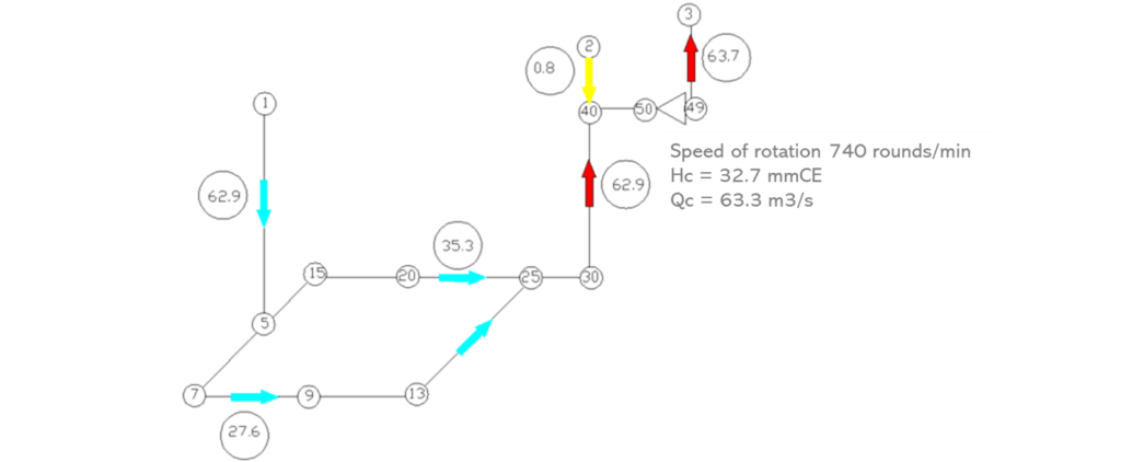
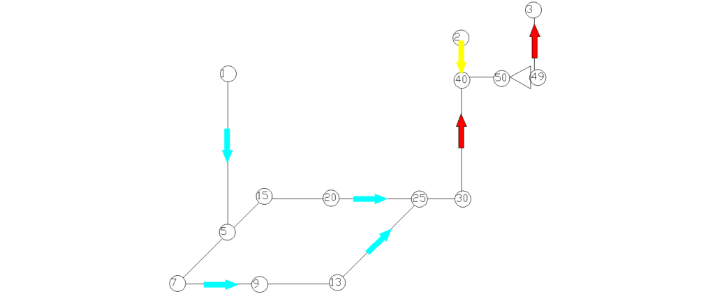
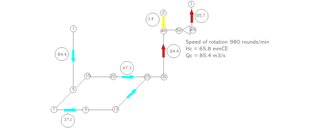
The diagram above shows an example of a ventilation network consisting of an air inlet shaft, an air return shaft and two connecting galleries between the shafts.
This network was modeled by calculation by introducing in the software :
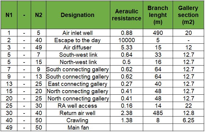
– The aeraulic resistances of the branches,
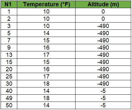
– The altitudes and temperatures of the knots,
– The characteristics of a main fan located at the top of the return air shaft,
– Daytime air pressure.
The following tables contain the input data for the calculation :
It can be seen that the total air flow increases from 63.3 to 84.4 m3/s and is shared between the north and south links with values respectively equal to 47.3 m3/s and 37.1 m3/s.
The main fan operates with a total pressure of 65.8 mmWE and a manufacturer’s air flow rate of 85.4 m3/s.
With efficiency assumptions equal to 0.8 for the fan and 0.95 for the motor, the electrical power consumed by the fan is equal to 73 kW.
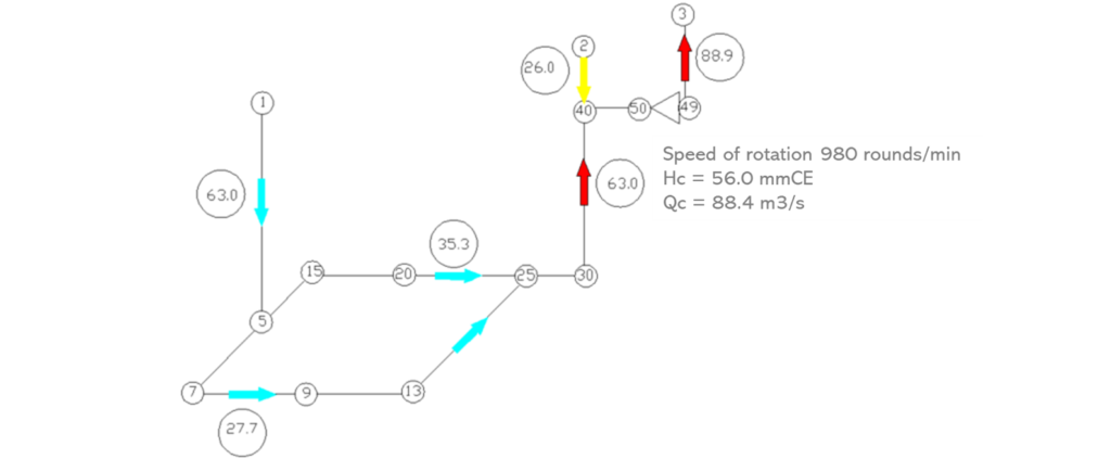
Consequence of the accidental opening of the SAS in the daytime
From the previous ventilation network (fan at 980 rpm), the accidental opening of the SAS during the day (branch 2-40) shows that the air flow rate of the SAS increases from 1.4 m3/s to 26 m3/s.
At the same time, the total air inlet flow rate decreases from 84.4 m3/s to 63 m3/s.
Calculation example of a network with a secondary ventilation line
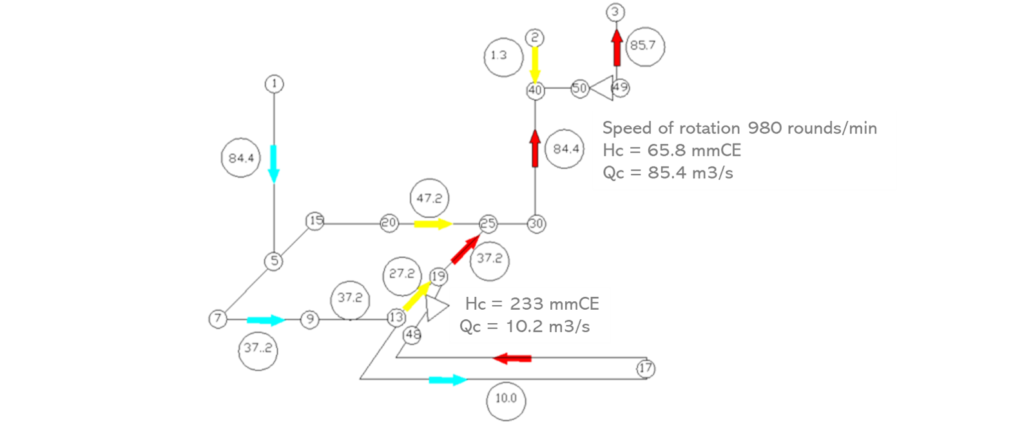
The diagram above shows the results of the calculation:
– With the fan at 980 rpm
– With a secondary suction ventilation line ventilating the excavation of gallery 13-17.
The air flow rate of the excavation in this example is equal to 10 m3/s (600 m3/min).
The secondary ventilation fan operates with a total pressure of 233 mmWE and a manufacturer’s air flow rate of 10.2 m3/s.
With efficiency assumptions equal to 0.8 for the fan and 0.95 for the motor, the electrical power consumed by the fan is equal to 31 kW.
The SUB’ROCA engineers are at your disposal to assist and advise you in the dimensioning of your ventilation installations. Whether your project concerns a meshed network in an underground mine or a complex digging project in another environment, our teams have the technology to calculate the air requirements and performance necessary to ensure ventilation that complies with the health and safety of personnel.

