How to measure an airflow ?
Determining the air flow rate
The knowledge of the air flow Q, implies the knowledge of the section S and the average velocity av in this section. There are different methods for determining the cross-section and average speed.
Section measurement
- Tables according to height and width
These tables only give correct results when the frames have their original shape and the floor is flat and horizontal. It is the simplest procedure but it leads to huge errors when applied indiscriminately to very irregular sections.
- Decomposition of the cross-section into simple geometric surfaces
A juxtaposition of simple figures is determined that corresponds as well as possible to the section that is to be estimated. We measure the dimensions that make it possible to calculate the surface area of these simple figures: semicircles, rectangles, trapezoids, triangles.
This process allows a quick evaluation of sections of any shape; however, no great accuracy is to be expected.


- Evaluation based on a grid of the section
This method, which the surveyors know how to implement, allows a very good precision if the points surveyed are tight enough; it is necessary to spend a rather long time at each station.
Note that polar coordinates are often more convenient than cartesian coordinates to perform the « grid », they allow the calculation of the section from measurements without planimetry.

- Photoprofile
This is the method used for measurements for ventilation studies. The operation at the bottom is fast and repetitive.
A photoprofile projector powered by a hat lamp is used for this purpose. The photo is taken with a camera.
We find on the photograph the luminous perimeter of the gallery as well as a square represented by 4 luminous points representing a surface of exactly 1m².
You have to start again if a photo was not successful, which is very rare, but under no circumstances can you get false results.
This method is very well suited to carrying out a series of measurements, two men can, in one position, survey up to 40 sections if the trips are not very long.

- Rectangular shaped gallery
The section S of a perfectly rectangular shaped gallery is calculated as follows :

- TH shape gallery
Section S of a « TH frame » shaped gallery is measured and calculated as follows :

Let K be a shape coefficient of the gallery
S = H*B*K
Special values of K :


Speed v measurement in galleries
- Speed distribution in a section
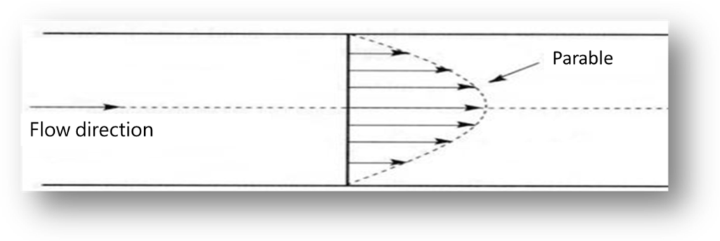
The speed at a point in a section depends on the position of that point and in particular its distance from the walls.
The areas close to the walls, where the speed is low, are of great importance as they represent a large proportion of the total section. Thus, the area between the outer storyteller of the section and a homothetic curve of it in the ratio 4/5 is equal to 36% of the total section, in a gallery framed in TH 420 the width of this crown is only 40cm; this important zone where the speed is low usually escapes the classical sweeping.

- Section choice
For a measurement to be accurate, a well-defined section should be chosen where :
-
- The flow is almost permanent, i.e. the velocity measured at a point varies little over time. Measurements should therefore be avoided when there are door manoeuvres or gear movements.
- The speed profile is regular. The proximity of obstacles such as equipment depots or stopped trains and doors that leak in the form of high-speed jets should be avoide.
- No fraction of the flow rate will escape the measurement. In particular, sections where there is a large gap between the lining and the ground should be avoided.
In principle, a straight, unencumbered gallery section should be chosen, with frames that are well aligned and well lined. Carefully mark the selected section for use in subsequent measurements.
- « Polar » measurement method
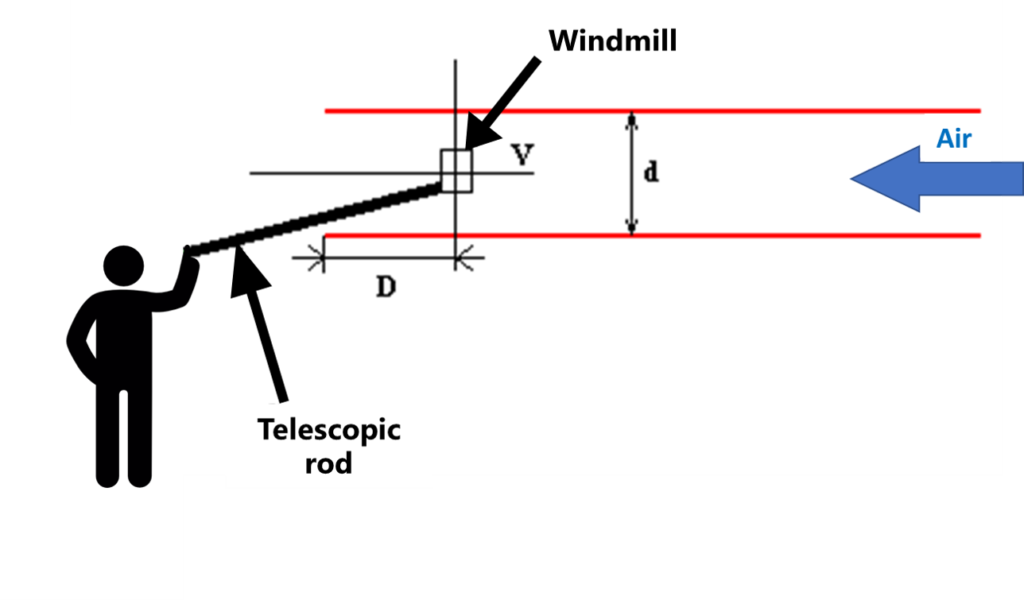
Measurements are made by an anemometer equipped with a telescopic rod.
This method consists of 21 measuring points divided into 3 radii r and a centre P.
The points P1, P2, P3 are distributed on a radius such that :
P3 = ½ r P2 = ¾ r P1 = 9/10 r
Note: to locate the measuring points, a rubber band marked with the marks P1 to P3 can be stretched.


- Simplified Polar Measurement Method
We will use the same material as for the polar method.
This method consists of 5 measuring points distributed 1 radius r and a centre P.
The P2 points are distributed over a radius such that:
P2 = ¾ r.


Operator positioning

If the operator is in the flow whose velocity he is measuring :
- He must ensure his own position in relation to the device
- Placed in the same section; it increases the air speed
- Placed immediately downstream airing, it reduces it
It must be placed between 1m and 1.50m downstream of the anemometer:
- Under these conditions, it changes the air speed little,
- This position also maintains the reel plane perpendicular to the direction of the airflow
If the measurement is carried out by two operators :
Whoever does not hold the reel should stand as far as possible downstream of the measuring point and against the facing.
The analysis
The samples taken must be returned to the specialised laboratory for analysis.
SF6 can be dosed on site using an electron capture device.
ANEMOMETERS
Air velocities are measured using electronic devices called anemometers.
There are mainly 2 types of anemometers: With reel or Bare wire
These devices can be accompanied by a processing software that allows the measurements to be exported to a computer.
- Reel anemometer
- Sensitive electronic devices.
- Measurement possible between 7 and 40 m/s at a temperature of 60°C or less, giving a direct or average reading if the instrument is equipped with this function.
- These devices are fragile and deserve regular maintenance to avoid clogging the reel, deforming the blades and thus disturbing the measurement.
There are different reel diameters:


- Bare-end anemometer
- Very sensitive electronic devices.
- Measurement possible below 7 m/s at a temperature less than or equal to 70°C, giving a direct or average reading if the instrument is equipped with this function.
- These devices are very fragile and deserve special attention to the bare wire at the end of the handle.

Calibration
Whatever the type of anemometer, it is necessary to calibrate it periodically; indeed, wear, dust, shocks modify the response curve.
An annual calibration and a calibration following any damage should be scheduled.
The SUB’ROCA engineers are at your disposal to assist and advise you in the dimensioning of your ventilation installations. Whether your project concerns a meshed network in an underground mine or a complex digging project in another environment, our teams have the technology to calculate the air requirements and performance necessary to ensure ventilation that complies with the health and safety of personnel.
